Network Requirements
- The whole network runs the PIM-SM protocol.
- Receiver1 and Receiver2 are the two receivers of Device3 end network.
- Device1 and Device2 are C-BSR and C-RP.
- Run IGMPv2 between Device3 and the end network.
Network Topology
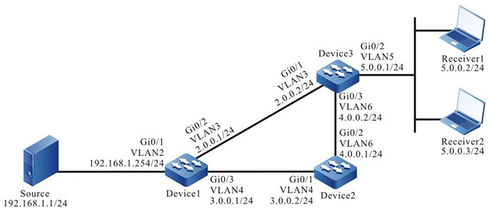
Figure 7-1 Networking of configuring PIM-SM basic functions
Configuration Steps
Step 1: Configure the IP address of the interface. (omitted)
Step 2: Enable the unicast route protocol OSPF so that all devices in the network can communicate with each other.
#Configure Device1.
|
Device1#configure terminal
Device1(config)#router ospf 100
Device1(config-ospf)#network 2.0.0.0 0.0.0.255 area 0
Device1(config-ospf)#network 3.0.0.0 0.0.0.255 area 0
Device1(config-ospf)#network 192.168.1.0 0.0.0.255 area 0
Device1(config-ospf)#exit
|
#Configure Device2.
|
Device2#configure terminal
Device2(config)#router ospf 100
Device2(config-ospf)#network 3.0.0.0 0.0.0.255 area 0
Device2(config-ospf)#network 4.0.0.0 0.0.0.255 area 0
Device2(config-ospf)#exit
|
#Configure Device3.
|
Device3#configure terminal
Device3(config)#router ospf 100
Device3(config-ospf)#network 2.0.0.0 0.0.0.255 area 0
Device3(config-ospf)#network 4.0.0.0 0.0.0.255 area 0
Device3(config-ospf)#exit
|
#View the route table of Device3.
Device3#show ip route
Codes: C - connected, S - static, R - RIP, O - OSPF, OE-OSPF External, M - Management
       D - Redirect, E - IRMP, EX - IRMP external, o - SNSP, B - BGP, i-ISIS

Gateway of last resort is not set

C 2.0.0.0/24 is directly connected, 14:48:47, vlan3
O 3.0.0.0/24 [110/2] via 2.0.0.1, 14:31:14, vlan3
             [110/2] via 4.0.0.1, 14:31:04, vlan6
C 4.0.0.0/24 is directly connected, 15:36:57, vlan6
C 5.0.0.0/24 is directly connected, 14:09:18, vlan5
O 192.168.1.0/24 [110/2] via 2.0.0.1, 00:30:55, vlan3

-
The viewing method of Device1 and device2 is the same as that of Device3, so the viewing process is omitted.
Step 3: Globally enable the multicast forwarding and enable the multicast protocol PIM-SM on the interface.
#Configure Device1.
Globally enable the multicast forwarding and enable the multicast protocol PIM-SM on the related interfaces.
|
Device1(config)#ip multicast-routing
Device1(config)#interface vlan2
Device1(config-if-vlan2)#ip pim sparse-mode
Device1(config-if-vlan2)#exit
Device1(config)#interface vlan3
Device1(config-if-vlan3)#ip pim sparse-mode
Device1(config-if-vlan3)#exit
Device1(config)#interface vlan4
Device1(config-if-vlan4)#ip pim sparse-mode
Device1(config-if-vlan4)#exit
|
#Configure Device2.
Globally enable the multicast forwarding and enable the multicast protocol PIM-SM on the related interfaces.
|
Device2(config)#ip multicast-routing
Device2(config)#interface vlan4
Device2(config-if-vlan4)#ip pim sparse-mode
Device2(config-if-vlan4)#exit
Device2(config)#interface vlan6
Device2(config-if-vlan6)#ip pim sparse-mode
Device2(config-if-vlan6)#exit
|
#Configure Device3.
Globally enable the multicast forwarding and enable the multicast protocol PIM-SM on the related interfaces.
|
Device3(config)#ip multicast-routing
Device3(config)#interface vlan3
Device3(config-if-vlan3)#ip pim sparse-mode
Device3(config-if-vlan3)#exit
Device3(config)#interface vlan5
Device3(config-if-vlan5)#ip pim sparse-mode
Device3(config-if-vlan5)#exit
Device3(config)#interface vlan6
Device3(config-if-vlan6)#ip pim sparse-mode
Device3(config-if-vlan6)#exit
|
#View the information of the interface enabled with the PIM-SM protocol on Device3 and the PIM-SM neighbor information.
Device3#show ip pim interface
PIM Interface Table:
PIM VRF Name: Default
Total 3 Interface entries
Total 0 External Interface entry
Total 0 Sparse-Dense Mode Interface entry

Address     Interface           VIF   Ver/   VIF   Nbr    DR       DR
BSR CISCO Neighbor
                               Index    Mode   Flag        Count        Pri
Border Neighbor Filter
2.0.0.2     vlan3                               0    v2/S   UP    1       1
2.0.0.2    FALSE FALSE
5.0.0.1     vlan5                2    v2/S   UP    0       1
5.0.0.1    FALSE FALSE
4.0.0.2     vlan6                               3    v2/S   UP    1       1
4.0.0.2    FALSE FALSE

Device3#show ip pim neighbor PIM Neighbor Table:
PIM VRF Name: Default Total 2 Neighbor entries
Neighbor    Interface     Uptime/Expires     Ver DR Priority/mode
Address
2.0.0.1     vlan3         01:12:00/00:01:39  v2  1  /
4.0.0.1     vlan6         01:13:19/00:01:35  v2  1  /
-
The viewing method of Device1 and device2 is the same as that of Device3, so the viewing process is omitted.
#View the IGMP information of interface VLAN5 of Device3.
Device3#show ip igmp interface vlan5
Interface vlan5 (Index 50332250)
 IGMP Active, Querier (5.0.0.1)
 Default version 2
 IP router alert option in IGMP V2 msgs: EXCLUDE
 Internet address is 5.0.0.1
 IGMP query interval is 125 seconds
 IGMP querier timeout is 255 seconds
 IGMP max query response time is 10 seconds
 Last member query response interval is 1 seconds
 Last member query count is 2
 Group Membership interval is 260 seconds
 IGMP robustness variable is 2

-
After configuring the multicast protocol on the interface, automatically enable the IGMP function and run IGMPv2 by default. You can configure the running IGMP version on the interface by executing the ip igmp version command.
Step 4: Configure interface vlan3 of Device1 as C-BSR and C-RP; configure the interface vlan4 of Device2 as C-BSR and C-RP.
#Configure Device1.
Configure interface vlan3 of Device1 as C-BSR and C-RP; the priority of C-BSR is 200; the multicast group range of the C-RP service is 230.0.0.0/8.
|
Device1(config)#ip pim bsr-candidate vlan 3 10 200
Device1(config)#ip access-list standard 1
Device1(config-std-nacl)#permit 230.0.0.0 0.255.255.255
Device1(config-std-nacl)#commit
Device1(config-std-nacl)#exit
Device1(config)#ip pim rp-candidate vlan 3 group-list 1
|
#Configure Device2.
Configure interface vlan4 of Device2 as C-BSR and C-RP; the priority of C-BSR is 0; the multicast group range of the C-RP service of Device2 is 230.0.0.0/4.
|
Device2(config)#ip pim bsr-candidate vlan4
Device2(config)#ip pim rp-candidate vlan4
|
#View the BSR and RP information of Device3.
Device3#show ip pim bsr-router
PIMv2 Bootstrap information
PIM VRF Name: Default
  BSR address: 2.0.0.1
  BSR Priority: 200
  Hash mask length: 10
  Up time: 01:03:30
  Expiry time: 00:01:46
  Role: Non-candidate BSR
  State: Accept Preferred

Device3#show ip pim rp mapping
PIM Group-to-RP Mappings Table:
PIM VRF Name: Default
Total 2 RP set entries
Total 2 RP entries

  Group(s): 224.0.0.0/4
  RP count: 1
    RP: 3.0.0.2
      Info source: 2.0.0.1, via bootstrap, priority 192
      Up time: 01:03:29
      Expiry time: 00:02:02

  Group(s): 230.0.0.0/8
  RP count: 1
    RP: 2.0.0.1
      Info source: 2.0.0.1, via bootstrap, priority 192
      Up time: 01:15:50
      Expiry time: 00:02:02
-
The viewing method of Device1 and device2 is the same as that of Device3, so the viewing process is omitted.
- When configuring multiple C-BSRs in one multicast domain, first elect BSR according to the priority and the C-BSR with the largest priority is elected as BSR. When the priorities of C-BSRs are the same, the C-BSR with the largest ip address is elected as BSR.
- When configuring multiple C-RPs in one multicast domain and the service multicast group ranges are the same, calculate the RP of the multicast group G according to the hash algorithm.
- In the multicast domain, you can configure RP via the command ip pim rp-address, but it is required that the static RP addresses configured on all devices in the multicast domain keep consistent.
Step 5: Check the result.
# Receiver1 and Receiver2 send the IGMPv2 member relation reports to add to multicast group 225.1.1.1, 230.1.1.1 respectively.
#Source sends the multicast packets with multicast group 225.1.1.1, 230.1.1.1. #View the multicast member table of Device3.
Device3#show ip igmp groups
IGMP Connected Group Membership Total 2 groups
Group Address    Interface   Uptime Expires     Last Reporter    V1 Expires
225.1.1.1        vlan5       00:56:48 00:02:39  5.0.0.2          stopped
230.1.1.1        vlan5       00:56:48 00:02:46  5.0.0.3          stopped
#View the RP of multicast group 225.1.1.1,230.1.1.1 on Device3.
Device3#show ip pim rp-hash 225.1.1.1
  PIM VRF Name: Default
  RP: 3.0.0.2
    Info source: 2.0.0.1, via bootstrap

Device3#show ip pim rp-hash 230.1.1.1
  PIM VRF Name: Default
  RP: 2.0.0.1
    Info source: 2.0.0.1, via bootstrap
#View the multicast route table of Device3.
Device3#show ip pim mroute
IP Multicast Routing Table:
PIM VRF Name: Default
Total 0 (*,*,RP) entry
Total 2 (*,G) entries
Total 2 (S,G) entries
Total 2 (S,G,rpt) entries
Total 0 FCR entry
Up timer/Expiry timer

(*, 225.1.1.1)
Up time: 00:36:21
RP: 3.0.0.2
RPF nbr: 4.0.0.1
RPF idx: vlan6
Flags:
  JOIN DESIRED
Upstream State: JOINED
  Local interface list:
    vlan5
  Joined interface list:
  Asserted interface list:

(192.168.1.1, 225.1.1.1)
Up time: 00:36:02
KAT time: 00:03:11
RPF nbr: 4.0.0.1
RPF idx: vlan6
SPT bit: TRUE
Flags:
  JOIN DESIRED
Upstream State: JOINED
  Local interface list:
  Joined interface list:
  Asserted interface list:
  Outgoing interface list:
    vlan5
  Packet count 2517423

(192.168.1.1, 225.1.1.1, rpt)
Up time: 00:36:02
RP: 3.0.0.2
Flags:

  RPT JOIN DESIRED
  PRUNE DESIRED
  RPF SGRPT XG EQUAL
Upstream State: PRUNED
  Local interface list:
  Pruned interface list:
  Outgoing interface list:
    vlan5

(*, 230.1.1.1)
Up time: 00:36:21
RP: 2.0.0.1
RPF nbr: 2.0.0.1
RPF idx: vlan3
Flags:
  JOIN DESIRED
Upstream State: JOINED
  Local interface list:
    vlan5
  Joined interface list:
  Asserted interface list:

(192.168.1.1, 230.1.1.1)
Up time: 00:36:02
KAT time: 00:03:11
RPF nbr: 2.0.0.1
RPF idx: vlan3
SPT bit: TRUE
Flags:
  JOIN DESIRED
Upstream State: JOINED
  Local interface list:
  Joined interface list:
  Asserted interface list:
  Outgoing interface list:
    vlan5
  Packet count 2517712

(192.168.1.1, 230.1.1.1, rpt)
Up time: 00:36:02 RP: 2.0.0.1
Flags:
  RPT JOIN DESIRED
  RPF SGRPT XG EQUAL
Upstream State: NOT PRUNED
  Local interface list:
  Pruned interface list:
  Outgoing interface list:
#Receiver1 can only receive the multicast service packet with multicast group 225.1.1.1 sent by Source. Receiver2 can only receive the multicast service packet with multicast group 230.1.1.1 sent by Source.
-
The viewing method of Device1 and Device2 is the same as that of Device3, so the viewing process is omitted.
- By default, the device enables the SPT switching.
 Switch


