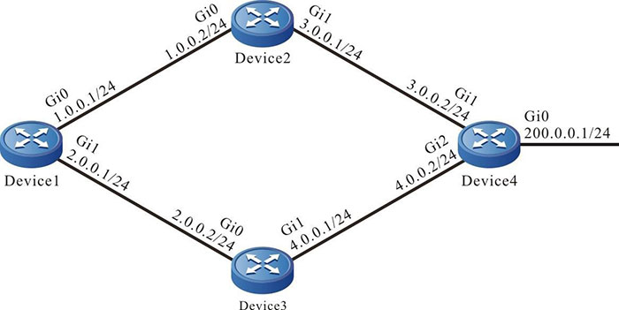
Network Requirements
- The IRMP protocol operates among Device1, Device2, Device3, and Device4 for interconnection.
- Device1 learns the routing 200.0.0.0/24 from Device2 and Device3 at the same time.
- Configure the routing metric offset at the receiving direction on Device1to enable Device1 to choose the routing advertised by Device2 preferentially.
Network Topology

Figure 11–3 Networking of the IRMP metric offset
Configuration Steps
Step 1: Configure the IP address of the interfaces. (Omitted)
Step 2: Configure the IRMP.
#Configure Device1.
|
Device1#configure terminal
Device1(config)#router irmp 100
Device1(config-irmp)#network 1.0.0.0 0.0.0.255
Device1(config-irmp)#network 2.0.0.0 0.0.0.255
Device1(config-irmp)#exit
|
#Configure Device2.
|
Device2#configure terminal
Device2(config)#router irmp 100
Device2(config-irmp)#network 1.0.0.0 0.0.0.255
Device2(config-irmp)#network 3.0.0.0 0.0.0.255
Device2(config-irmp)#exit
|
#Configure Device3.
|
Device3#configure terminal
Device3(config)#router irmp 100
Device3(config-irmp)#network 2.0.0.0 0.0.0.255
Device3(config-irmp)#network 4.0.0.0 0.0.0.255
Device3(config-irmp)#exit
|
#Configure Device4.
|
Device4#configure terminal
Device4(config)#router irmp 100
Device4(config-irmp)#network 3.0.0.0 0.0.0.255
Device4(config-irmp)#network 4.0.0.0 0.0.0.255
Device4(config-irmp)#network 200.0.0.0 0.0.0.255
Device4(config-irmp)#exit
|
#View the IRMP neighbor inofrmation of Device1.
Device1#show ip irmp neighbor
IP-IRMP neighbors for process 100 Total neighbor 2
Address     Interface            Hold(s) Uptime   SeqNum   Srtt(ms) Rto(s)
1.0.0.2     gigabitethernet0     11      00:10:37 10       0        2
2.0.0.2     gigabitethernet1     12      00:10:15 9        0        2
#View the IRMP neighbor information of Device4.
Device4#show ip irmp neighbor
IP-IRMP neighbors for process 100 Total neighbor 2
Address     Interface            Hold(s) Uptime   SeqNum   Srtt(ms) Rto(s)
3.0.0.1     gigabitethernet1     14      00:11:37 13       0        2
4.0.0.1     gigabitethernet2     12      00:10:45 12       0        2
Device1 successfully establishes the IRMP neighbor with Device2 and Device3, respectively. Device4 successfully establishes the IRMP neighbor with Device2 and Device3, respectively.
#View the topology table and routing table of Device1.
Device1#show ip irmp topology
IP-IRMP Topology Table for process 100
Codes: P - Passive, A - Active, H - Holddown, D - Hidden
        > - FIB route, * - FIB successor

P >1.0.0.0/24, 1 successors, FD is 2816
        *via Connected (2816/0), gigabitethernet0
P >2.0.0.0/24, 1 successors, FD is 2816
        *via Connected (2816/0), gigabitethernet1
P >3.0.0.0/24, 1 successors, FD is 3072
        *via 1.0.0.2 (3072/2816), gigabitethernet0
P >4.0.0.0/24, 1 successors, FD is 3072
        *via 2.0.0.2 (3072/512), gigabitethernet1
P >200.0.0.0/24, 2 successors, FD is 3328
        *via 2.0.0.2 (3328/3072), gigabitethernet1
        *via 1.0.0.2 (3328/3072), gigabitethernet0

Device1#show ip route
Codes: C - connected, S - static, R - RIP, O - OSPF, OE-OSPF External, M - Management
       D - Redirect, E - IRMP, EX - IRMP external, o - SNSP, B - BGP, i-ISIS

Gateway of last resort is not set

C 1.0.0.0/24 is directly connected, 13:16:35, gigabitethernet0
C 2.0.0.0/24 is directly connected, 13:19:24, gigabitethernet1
E 3.0.0.0/24 [90/3072] via 1.0.0.2, 00:03:22, gigabitethernet0
E 4.0.0.0/24 [90/3072] via 2.0.0.2, 00:22:01, gigabitethernet1
C 127.0.0.0/8 is directly connected, 22:27:25, lo0
E 200.0.0.0/24 [90/3328] via 2.0.0.2, 00:21:22, gigabitethernet1
                 [90/3328] via 1.0.0.2, 00:03:22, gigabitethernet0
There are two load balancing routing to the network segment 200.0.0.0/24 in Device1 routing table. The forwarding paths to the network segment are Device1→ Device2→ Device4 and Device1→ Device3→ Device4.
Step 3: Configure the IRMP metric offset.
#Configure the offset list on Device1. Add metric value 100 to the interface connected to Device3 by the specified routing to enable the total metric value going through Device3 is larger than that going through Device2.
|
Device1(config)#ip access-list standard 1
Device1(config-std-nacl)#permit 200.0.0.0 0.0.0.255
Device1(config-std-nacl)#exit
Device1(config)#router irmp 100
Device1(config-irmp)#offset-list 1 in 100 gigabitethernet1
Device1(config-irmp)#exit
|
Step 4: Check the result.
#View the topology table and routing table of Device1.
Device1#show ip irmp topology
IP-IRMP Topology Table for process 100
Codes: P - Passive, A - Active, H - Holddown, D - Hidden
        > - FIB route, * - FIB successor

P >1.0.0.0/24, 1 successors, FD is 2816
        *via Connected (2816/0), gigabitethernet0
P >2.0.0.0/24, 1 successors, FD is 2816
        *via Connected (2816/0), gigabitethernet1
P >3.0.0.0/24, 1 successors, FD is 3072
        *via 1.0.0.2 (3072/2816), gigabitethernet0
P >4.0.0.0/24, 1 successors, FD is 3072
        *via 2.0.0.2 (3072/512), gigabitethernet1
P >200.0.0.0/24, 2 successors, FD is 3328
        *via 1.0.0.2 (3328/3072), gigabitethernet0
         via 2.0.0.2 (3428/3172), gigabitethernet1

Device1#show ip route
Codes: C - connected, S - static, R - RIP, O - OSPF, OE-OSPF External, M - Management
       D - Redirect, E - IRMP, EX - IRMP external, o - SNSP, B - BGP, i-ISIS

Gateway of last resort is not set

C 1.0.0.0/24 is directly connected, 13:33:22, gigabitethernet0
C 2.0.0.0/24 is directly connected, 13:36:11, gigabitethernet1
E 3.0.0.0/24 [90/3072] via 1.0.0.2, 00:06:56, gigabitethernet0
E 4.0.0.0/24 [90/3072] via 2.0.0.2, 00:05:43, gigabitethernet1
C 127.0.0.0/8 is directly connected, 22:44:12, lo0
E 200.0.0.0/24 [90/3328] via 1.0.0.2, 00:06:56, gigabitethernet0
After the metric offset is configured, Device1 chooses the routing 200.0.0.0/24 advertised by Device2.

-
Configuring the IRMP offset list may cause the neighbor to be reestablished.
 Switch
 Wifi - Access Point
 Firewall
 Router
 Module Quang
![Module Quang Cisco]() Module Quang Cisco
Module Quang Cisco![Module quang HPE]() Module quang HPE
Module quang HPE![Module quang Maipu]() Module quang Maipu
Module quang Maipu![Module quang Brocade]() Module quang Brocade
Module quang Brocade![Module quang Fortinet]() Module quang Fortinet
Module quang Fortinet![Module quang Aruba]() Module quang Aruba
Module quang Aruba![Module quang OEM]() Module quang OEM
Module quang OEM![Module quang Juniper]() Module quang Juniper
Module quang Juniper![Module quang Dell]() Module quang Dell
Module quang Dell![Module quang Palo Alto]() Module quang Palo Alto
Module quang Palo Alto![Module quang Huawei]() Module quang Huawei
Module quang Huawei![Module quang Arista]() Module quang Arista
Module quang Arista![Module quang F5]() Module quang F5
Module quang F5![Module quang H3C]() Module quang H3C
Module quang H3C![Module Quang Allied Telesis]() Module Quang Allied Telesis
Module Quang Allied Telesis![Module quang SonicWall]() Module quang SonicWall
Module quang SonicWall![Module quang Mikrotik]() Module quang Mikrotik
Module quang Mikrotik![Module quang Handar]() Module quang Handar
Module quang Handar Máy chủ (Server)
 Thiết bị lưu trữ (SAN, NAS)
 Load Balancing
 Video Conferencing
 Phụ kiện máy chủ
 Thiết Bị IoT
 Phụ Kiện Mạng


.png)


