Network Requirements
- The whole network runs the IPv6 PIM-SSM protocol.
- PC1 and PC2 are the two receivers of Device3 stub network.
- Device1 and Device2 are C-BSR and C-RP.
- Run MLDv2 between Device3 and the stub network.
Network Topology
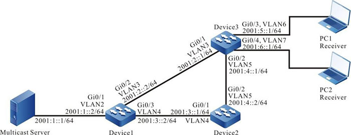
Figure 11-1 Networking of configuring IPv6 PIM-SM basic functions
Configuration Steps
Step 1: Configure VLAN, and add the port to the corresponding VLAN (omitted).
Step 2: Configure the IPv6 address of the interface. (omitted)
Step 3: Enable unicast routing protocol OSPFv3 so that all devices in the network can communicate with each other.
#Configure Device1.
|
Device1#configure terminal
Device1(config)#ipv6 router ospf 100
Device1(config-ospf6)#router-id 1.1.1.1
Device1(config-ospf6)#exit
Device1(config)#interface vlan2
Device1(config-if-vlan2)#ipv6 router ospf 100 area 0
Device1(config-if-vlan2)#exit
Device1(config)#interface vlan3
Device1(config-if-vlan3)#ipv6 router ospf 100 area 0
Device1(config-if-vlan3)#exit
Device1(config)#interface vlan4
Device1(config-if-vlan4)#ipv6 router ospf 100 area 0
Device1(config-if-vlan4)#exit
|
#Configure Device2.
|
Device2#configure terminal
Device2(config)#ipv6 router ospf 100
Device2(config-ospf6)#router-id 2.2.2.2
Device2(config-ospf6)#exit
Device2(config)#interface vlan4
Device2(config-if-vlan4)#ipv6 router ospf 100 area 0
Device2(config-if-vlan4)#exit
Device2(config)#interface vlan5
Device2(config-if-vlan5)#ipv6 router ospf 100 area 0
Device2(config-if-vlan5)#exit
|
#Configure Device3.
|
Device3#configure terminal
Device3(config)#ipv6 router ospf 100
Device3(config-ospf6)#router-id 3.3.3.3
Device3(config-ospf6)#exit
Device3(config)#interface vlan3
Device3(config-if-vlan3)#ipv6 router ospf 100 area 0
Device3(config-if-vlan3)#exit
Device3(config)#interface vlan5
Device3(config-if-vlan5)#ipv6 router ospf 100 area 0
Device3(config-if-vlan5)#exit
Device3(config)#interface vlan6
Device3(config-if-vlan6)#ipv6 router ospf 100 area 0
Device3(config-if-vlan6)#exit
Device3(config)#interface vlan7
Device3(config-if-vlan7)#ipv6 router ospf 100 area 0
Device3(config-if-vlan7)#exit
|
#Query the route table of Device3.
Device3#show ipv6 route
Codes: C - Connected, L - Local, S - static, R - RIP, B - BGP, i-ISIS
       U - Per-user Static route
       O - OSPF, OE-OSPF External, M - Management


L ::1/128 [0/0]
     via ::, 2w6d:04:39:46, lo0
O 2001:1::/64 [110/2]
     via fe80::201:7aff:fe62:bb7e, 00:00:24, vlan3
C  2001:2::/64 [0/0]
     via ::, 00:01:05, vlan3
L 2001:2::1/128 [0/0]
     via ::, 00:01:04, lo0
O 2001:3::/64 [110/2] via fe80::201:7aff:fe62:bb7e, 00:00:24, vlan3
              [110/2] via fe80::201:7aff:fec0:525a, 00:00:04, vlan5
C  2001:4::/64 [0/0]
     via ::, 00:00:49, vlan5
L 2001:4::1/128 [0/0]
     via ::, 00:00:48, lo0
C 2001:5::/64 [0/0]
     via ::, 00:00:43, vlan6
L 2001:5::1/128 [0/0]
     via ::, 00:00:42, lo0
C 2001:6::/64 [0/0]
     via ::, 00:00:43, vlan7
L 2001:6::1/128 [0/0]
     via ::, 00:00:42, lo0

-
The query methods of Device1 and Device2 are the same as that of Device3, so the query process is omitted.
Step 4: Globally enable IPv6 multicast forwarding, and enable the multicast protocol IPv6 PIM-SM on the interface.
#Configure Device1.
Globally enable IPv6 multicast forwarding, and enable the multicast protocol IPv6 PIM-SM on the related interface.
|
Device1(config)#ipv6 multicast-routing
Device1(config)#interface vlan2
Device1(config-if-vlan2)#ipv6 pim sparse-mode
Device1(config-if-vlan2)#exit
Device1(config)#interface vlan3
Device1(config-if-vlan3)#ipv6 pim sparse-mode
Device1(config-if-vlan3)#exit
Device1(config)#interface vlan4
Device1(config-if-vlan4)#ipv6 pim sparse-mode
Device1(config-if-vlan4)#exit
|
#Configure Device2.
Globally enable the IPv6 multicast forwarding, and enable the multicast protocol IPv6 PIM-SM on the related interface.
|
Device2(config)#ipv6 multicast-routing
Device2(config)#interface vlan4
Device2(config-if-vlan4)#ipv6 pim sparse-mode
Device2(config-if-vlan4)#exit
Device2(config)#interface vlan5
Device2(config-if-vlan5)#ipv6 pim sparse-mode
Device2(config-if-vlan5)#exit
|
#Configure Device3.
Globally enable the IPv6 multicast forwarding, and enable the multicast protocol IPv6 PIM-SM on the related interface.
|
Device3(config)#ipv6 multicast-routing
Device3(config)#interface vlan3
Device3(config-if-vlan3)#ipv6 pim sparse-mode
Device3(config-if-vlan3)#exit
Device3(config)#interface vlan5
Device3(config-if-vlan5)#ipv6 pim sparse-mode
Device3(config-if-vlan5)#exit
Device3(config)#interface vlan6
Device3(config-if-vlan6)#ipv6 pim sparse-mode
Device3(config-if-vlan6)#exit
Device3(config)#interface vlan7
Device3(config-if-vlan7)#ipv6 pim sparse-mode
Device3(config-if-vlan7)#exit
|
#Query the information about the interface enabled with the IPv6 PIM-SM protocol on Device3, and IPv6 PIM-SM neighbor information.
Device3#show ipv6 pim interface
PIM6 Interface Table:
PIM6 VRF Name: Default
Total 5 Interface entries
Total 0 External Interface entry
Total 0 Sparse-Dense Mode Interface entry

Interface    VIF   Ver/ VIF  Nbr   DR   BSR    CISCO    Neighbor
             Index Mode Flag Count Pri  Border Neighbor Filter
register_vif0   2     v2/S UP
Address : fe80::201:7aff:fe5e:6d2d Global Address: ::

vlan3        1      v2/S UP   1     1    FALSE FALSE
Address : fe80::201:7aff:fe5e:6d2d        Global Address: 2001:2::1               DR: fe80::201:7aff:fe62:bb7e

vlan5      3     v2/S UP   1     1    FALSE FALSE
Address : fe80::201:7aff:fe5e:6d2e        Global Address: 2001:4::1               DR: fe80::201:7aff:fec0:525a

vlan6      4     v2/S UP   0     1    FALSE FALSE
Address : fe80::201:7aff:fe5e:6d2f        Global Address: 2001:5::1               DR: fe80::201:7aff:fe5e:6d2f

vlan7      5     v2/S UP   0     1    FALSE FALSE
Address : fe80::201:7aff:fe5e:6d30        Global Address: 2001:6::1               DR: fe80::201:7aff:fe5e:6d30

Device3#show ipv6 pim neighbor
PIM6 Neighbor Table:
PIM6 VRF Name: Default
Total 2 Neighbor entries

Neighbor                  Interface   Uptime/Expires     Ver DR
Address                                                  Priority/Mode
fe80::201:7aff:fe62:bb7e  vlan3       00:04:01/00:01:29  v2 1 / DR
fe80::201:7aff:fec0:525a  vlan5       00:04:03/00:01:39  v2 1 / DR
-
The query methods of Device1 and Device2 is the same as that of Device3, and the querying process is omitted.
Step 5: On vlan6 and vlan7 of Device3, enable MLD.
#Configure Device3.
On vlan6 and vlan7 of Device3, enable MLD.
|
Device3(config)#interface vlan6
Device3(config-if-vlan6)#ipv6 mld enable
Device3(config-if-vlan6)#exit
Device3(config)#interface vlan7
Device3(config-if-vlan7)#ipv6 mld enable
Device3(config-if-vlan7)#exit
|
#Query the MLD information of interface vlan6 and vlan7 on Device3.
Device3#show ipv6 mld interface
Interface vlan6 (Index 11)
 MLD Enabled, Active
 Querier: fe80::201:7aff:fe5e:6d2f (Self)
 Default version: 2
 Querier parameter:
   Query interval is 125 seconds
   Querier timeout is 255 seconds
   Query response time is 10 seconds
   Last member query response interval is 1 seconds
   Last member query count is 2
   Group Membership interval is 260 seconds
   Robustness variable is 2
Interface vlan7 (Index 12)
 MLD Enabled, Active
 Querier: fe80::201:7aff:fe5e:6d30 (Self)
 Default version: 2
 Querier parameter:
   Query interval is 125 seconds
   Querier timeout is 255 seconds
   Query response time is 10 seconds
   Last member query response interval is 1 seconds
   Last member query count is 2
   Group Membership interval is 260 seconds
   Robustness variable is 2
-
You can configure the MLD version running on the interface via the ip v6 mld version command.
Step 6: Configure the interface vlan3 of Device1 as C-BSR and C-RP, and configure the interface vlan4 of Device2 as C-BSR and C-RP.
#Configure Device1.
Configure interface vlan3 of Device1 as C-BSR and C-RP, the priority of C-BSR is 200, and the multicast group range of the C-RP service is FF10::/16.
|
Device1(config)#ipv6 pim bsr-candidate vlan3 10 200
Device1(config)#ipv6 access-list extended 7001
Device1(config-v6-list)#permit ipv6 any ff10::/16
Device1(config-v6-list)#commit
Device1(config-v6-list)#exit
Device1(config)#ipv6 pim rp-candidate vlan3 group-list 7001
|
#Configure Device2.
Configure interface vlan4 of Device2 as C-BSR and C-RP, the priority of C-BSR is 0, and the multicast group range of the C-RP service is FF00::/8.
|
Device2(config)#ipv6 pim bsr-candidate vlan4
Device2(config)#ipv6 pim rp-candidate vlan4
|
#Query the BSR and RP information of Device3.
Device3#show ipv6 pim bsr-router
PIM6v2 Bootstrap information
PIM6 VRF Name: Default
  BSR address: 2001:2::2
  BSR Priority: 200
  Hash mask length: 10
  Up time: 00:03:04
  Expiry time: 00:02:06
  Role: Non-candidate BSR
  State: Accept Preferred

Device3#show ipv6 pim rp mapping
PIM6 Group-to-RP Mappings Table:
PIM6 VRF Name: Default
Total 2 RP set entries
Total 2 RP entries

  Group(s): ff00::/8
  RP count: 1
    RP: 2001:3::1
      Info source: 2001:2::2, via bootstrap, priority 192
      Up time: 00:21:30
      Expiry time: 00:02:24

  Group(s): ff10::/16
  RP count: 1
    RP: 2001:2::2
      Info source: 2001:2::2, via bootstrap, priority 192
      Up time: 00:04:31
      Expiry time: 00:02:24
-
The query methods of Device1 and Device2 are the same as that of Device3, and the query process is omitted.
- When configuring multiple C-BSRs in a multicast domain, BSR will be selected first according to priority, and the C-BSR with the highest priority will be selected as BSR. When the priorities of C-BSRs are the same, the C-BSR with the largest IP address is selected as BSR.
- When multiple C-RPs are configured in a multicast domain and the multicast group range of the service is the same, the corresponding RP of multicast group G will be calculated according to the hash algorithm.
- In the multicast domain, you can configure RP by the command ipv6 pim rp-address, but the static RP addresses configured on all devices of the entire multicast domain are required to be consistent.
Step 7: Check the result.
#PC1 and PC2 respectively send MLDv2 member relation report to add to multicast group FF10::1 and FF50::1.
#Multicast Server sends the multicast service packet of multicast group FF10::1, FF50::1.
#Query the multicast member table on Device3.
Device3#show ipv6 mld groups MLD Connected Group Membership Total 2 Connected Groups
Group      Interface  Uptime    Expires  V1-Expires Last Reporter
ff10::1    vlan6      00:00:09  00:04:13 not used   fe80::210:94ff:fe00:1
ff50::1    vlan7      00:00:09  00:04:14 not used   fe80::210:94ff:fe00:2
#Query the RP of multicast group FF10::1, FF50::1 on Device3.
Device3#show ipv6 pim rp-hash ff10::1
  PIM6 VRF Name: Default
  RP: 2001:2::2
    Info source: 2001:2::2, via bootstrap

Device3#show ipv6 pim rp-hash ff50::1
  PIM6 VRF Name: Default
  RP: 2001:3::1
    Info source: 2001:2::2, via bootstrap
#Query the multicast route table of Device3.
Device3#show ipv6 pim mroute
IP Multicast Routing Table:
PIM6 VRF Name: Default
Total 0 (*,*,RP) entry
Total 2 (*,G) entries
Total 2 (S,G) entries
Total 2 (S,G,rpt) entries
Total 0 FCR entry
Up timer/Expiry timer

(*, ff10::1)
Up time: 00:00:06
RP: 2001:2::2
RPF nbr: fe80::201:7aff:fe62:bb7e
RPF idx: vlan3

Flags:
  JOIN DESIRED
Upstream State: JOINED
  Local interface list:
    vlan6
  Joined interface list:
  Asserted interface list:


(2001:1::1, ff10::1)
Up time: 00:00:05
KAT time: 00:03:25
RPF nbr: fe80::201:7aff:fe62:bb7e
RPF idx: vlan3
SPT bit: TRUE
Flags:
  JOIN DESIRED
Upstream State: JOINED
  Local interface list:
  Joined interface list:
  Asserted interface list:
  Outgoing interface list:
    vlan6
  Packet count 0

(2001:1::1, ff10::1, rpt)
Up time: 00:00:05
RP: 2001:2::2
Flags:
  RPT JOIN DESIRED
  RPF SGRPT XG EQUAL
Upstream State: NOT PRUNED
  Local interface list:
  Pruned interface list:
  Outgoing interface list:

(*, ff50::1)
Up time: 00:00:06
RP: 2001:3::1
RPF nbr: fe80::201:7aff:fec0:525a
RPF idx: vlan5
Flags:
  JOIN DESIRED
Upstream State: JOINED
  Local interface list:
    vlan7
  Joined interface list:
  Asserted interface list:

(2001:1::1, ff50::1)
Up time: 00:00:05
KAT time: 00:03:27
RPF nbr: fe80::201:7aff:fe62:bb7e
RPF idx: vlan3
SPT bit: TRUE
Flags:
  JOIN DESIRED
Upstream State: JOINED
  Local interface list:
  Joined interface list:
  Asserted interface list:
  Outgoing interface list:
    vlan7
  Packet count 1

(2001:1::1, ff50::1, rpt)
Up time: 00:00:05
RP: 2001:3::1
Flags:
  RPT JOIN DESIRED
  PRUNE DESIRED
  RPF SGRPT XG EQUAL
Upstream State: PRUNED
  Local interface list:
  Pruned interface list:
  Outgoing interface list:
    vlan7
#PC1 can only receive multicast service packets sent by Multicast Server, whose multicast group is FF10::1. PC2 can only receive multicast service packets sent by Multicast Server, whose multicast group is FF50::1.
-
The query methods of Device1 and Device2 are the same as that of Device3, so the query method is omitted.
- By default, the device enables the SPT switching.
 Switch


