Configure NTP Broadcast Mode
Network Requirements
- Device1, Device2, and Device3 are interconnected via their interfaces; the route is reachable.
- Device1 sets the local clock as the reference clock and the number of the layers is 3.
- Device1 is the NTP broadcast server and sends the NTP broadcast packet from the interface vlan2.
- Device2 and Device3 are the NTP broadcast client, monitoring the NTP broadcast packet on their interface vlan2.
Network Topology
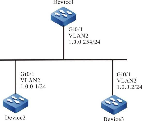
Figure 4-5 Networking of configuring the NTP broadcast mode
Configuration Steps
Step 1: Configure the IP address of the interface. (omitted)
Step 2: Device1 sets the local clock as the reference clock and the number of the layers is 3; configure Device1 as the NTP broadcast server, sending the NTP broadcast packet from the interface vlan2.
#On Device1, enable NTP IPv4, and configure the time zone as Beijing time zone, and the number of the local clock layers as 3.
|
Device1#configure terminal
Device1(config)#ntp enable
Device1(config)#clock timezone BINJING 8
Device1(config)#ntp master 3
|
#Configure Device1 as the NTP broadcast server, sending the NTP broadcast packet from the interface vlan2.
|
Device1(config)#interface vlan2
Device1(config-if-vlan2)#ntp broadcast-server
|
Step 3: Configure Device2 as the NTP broadcast client, monitoring the NTP broadcast packet on the interface vlan2.
|
Device2#configure terminal
Device2(config)#ntp enable
Device2(config)#clock timezone BINJING 8
Device2(config)#interface vlan2
Device2(config-if- vlan2)#ntp broadcast-client
|
Step 4: Configure Device3 as the NTP broadcast client, monitoring the NTP broadcast packet on the interface vlan2.
|
Device3#configure terminal
Device3(config)#ntp enable
Device3(config)#clock timezone BINJING 8
Device3(config)#interface vlan2
Device3(config-if- vlan2)#ntp broadcast-client
|
Step 5: Check the result.
#Execute the show ntp status command on the client Device2 and view the clock synchronization status information.
|
Device2#show ntp status
Current NTP status information
NTP ipv4 is enabled
NTP ipv6 is disabled
Clock is synchronized, stratum 4, reference is 1.0.0.254
reference time is D8E97C99.5110D9FE (03:27:21.316 Tue Apr 28 2015)
|
The number of Device2 clock layers is 4, larger than Device1 by 1, and the reference clock server address is 1.0.0.254, indicating that the client Device2 is already synchronized with the server Device1.
#Execute the show clock command to view the device clock on the client Device2.
|
Device2#show clock
BEIJING(UTC+08:00) TUE APR 28 11:27:22 2015
|
#Execute the show ntp status command on the active peer Device3 and view the clock synchronization status information.
|
Device3#show ntp status
Current NTP status information
NTP ipv4 is enabled
NTP ipv6 is disabled
Clock is synchronized, stratum 4, reference is 1.0.0.254
reference time is D8E97CAC.78F42CA6 (03:27:40.472 Tue Apr 28 2015)
|
The layers of Device3 clock is 4, larger than Device1 by 1, and the reference clock server address is 1.0.0.254, indicating that the active peer Device3 is already synchronized with the server Device1.
#Execute the show clock command to view the device clock on client Device3.
|
Device3#show clock
BEIJING(UTC+08:00) TUE APR 28 11:27:41 2015
|
 Switch


