Network Requirements
- Four devices form the dual-uplink networking. The uplink devices are Device1, Device2, and Device3; the downlink device is Device4.
- Configure the Monitor Link function on Device3, realizing the monitoring of the link fault.
- When the uplink port of the Monitor Link group fails, disable the downlink port, causing the master/slave link switchover of the ULPP group and ensuring the connectivity of the network.
Network Topology
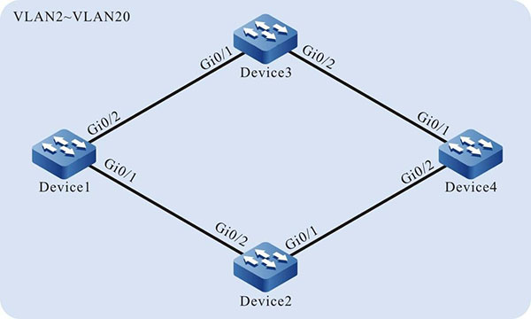
Figure 4-2 Networking of configuring Monitor Link
Configuration Steps
Step 1: Configure the link type of the VLAN and port.
#Create VLAN2-VLAN20 on Device1, configure the link type of port gigabiteternet0/1, gigabiteternet0/2 on Device1 as Trunk; permit the services of VLAN2-VLAN20 to pass.
|
Device1#configure terminal
Device1(config)#vlan 2-20
Device1(config)#interface gigabitethernet 0/1
Device1(config-if-gigabitethernet0/1)#switchport mode trunk
Device1(config-if-gigabitethernet0/1)#switchport trunk allowed vlan add 2-20
Device1(config-if-gigabitethernet0/1)#exit
Device1(config)#interface gigabitethernet 0/2
Device1(config-if-gigabitethernet0/2)#switchport mode trunk
Device1(config-if-gigabitethernet0/2)#switchport trunk allowed vlan add 2-20
Device1(config-if-gigabitethernet0/2)#exit
|

-
The configuration of the port and link type of Device2, Device3, and Device4 is the same as that of Device1. (Omitted)
Step 2: Configure the spanning tree instance on Device4.
#Configure the spanning tree instance; instance 1 maps VLAN3-VLAN10; instance 2 maps VLAN11-VLAN20.
|
Device4(config)#spanning-tree mst configuration
Device4(config-mst)#region-name admin
Device4(config-mst)#revision-level 1
Device4(config-mst)#instance 1 vlan 3-10
Device4(config-mst)#instance 2 vlan 11-20
|
#Enable the spanning tree instance.
|
Device4(config-mst)#active configuration pending
Device4(config-mst)#exit
|
Step 3: Configure the ULPP function on Device4.
|
Device4(config)#ulpp-group 1
Device4(config-ulpp-1)#master interface gigabitethernet 0/1
Device4(config-ulpp-1)#slave interface gigabitethernet 0/2
Device4(config-ulpp-1)#instance group 1 master
Device4(config-ulpp-1)#instance group 2 slave
Device4(config-ulpp-1)#mode backup
Device4(config-ulpp-1)#control-vlan 2
Device4(config-ulpp-1)#flush enable
Device4(config-ulpp-1)#enable
Device4(config-ulpp-1)#exit
|
-
After VLAN2 is configured as control VLAN, only the Flush packets can pass in the VLAN, but the other service packets cannot.
Step 4: Configure the uplink device Device1, Device2 and Device3.
#Configure the receiving and sending mechanism of the Flush packets on Device1.
|
Device1(config)#interface gigabitethernet 0/1-0/2
Device1(config-if-range)#ulpp flush control-vlan 2
Device1(config-if-range)#exit
|
-
The receiving and forwarding mechanism of Device2 and Device3 is the same as that of Device1. (Omitted)
Step 5: Configure the Monitor Link group.
#Create the Monitor Link group on Device3.
|
Device3(config)#mtlk-group 1
|
#Configure gigabitethernet0/1 as the uplink port of the Monitor Link group on Device3.
|
Device3(config-mtlk-1)#uplink interface gigabitethernet 0/1
|
#Configure gigabitethernet0/2 as the downlink port of the Monitor Link group on Device3.
|
Device3(config-mtlk-1)#downlink interface gigabitethernet 0/2
|
#View the Monitor Link group.
Device3#show mtlk group 1
---------------------------------------
mtlk-group 1 configuration information
---------------------------------------
Uplink interface	: gi0/1
Uplink type         : no-ulpp
Uplink status       : up
Downlink interface	: gi0/2
Step 6: Check the result.
#After the uplink port gigabitethernet0/1 of the uplink device Device3 fails, the status of the downlink port gigabitethernet0/2 keeps linkage with the status of the uplink port gigabitethernet0/1. The downlink port is forced to be disabled.
#View the status of the downlink port gigabitethernet0/2.
Device3#show interface gigabitethernet 0/2
gigabitethernet0/2 configuration information
Description      : downlink
Status           : Enabled
Link             : Down (Err-disabled)
Set Speed        : Auto
Act Speed        : Unknown
Set Duplex       : Auto
Act Duplex       : Unknown Set Flow Control : Off
Act Flow Control : Off Mdix	: Auto
Mtu               1824
Port mode	     : LAN
Port ability	 : 10M HD,10M FD,100M HD,100M FD,1000M FD
Link Delay	     : No Delay
Storm Control	 : Unicast Disabled
Storm Control	 : Broadcast Disabled
Storm Control	 : Multicast Disabled
Storm Action	 : None
Port Type	     : Nni
Pvid              1
Set Medium       : Copper
Act Medium       : Copper
Mac Address      : 0001.7a58.000b
The downlink port gigabitethernet0/2 is disabled, causing the master/slave link switchover of the ULPP group of Device4 and ensuring the connectivity of the network.
 Switch


