Network Requirements
- The IRMP protocol operates among Device1, Device2, Device3, and Device4 for routing interaction,
- Device1 learns the routing 200.0.0.0/24 from Device2 and Device3 at the same time. Modify the bandwidth of interface gigabitethernet1 on Device1 to enable Device1 to preferentially choose the routing 200.0.0.0/24 learned from Device2.
- Device1 is required to transfer data to the network segment200.0.0.0/24 simultaneously on lines Device1→Device2→Device4 and Device1→Device3→Device4.
Network Topology
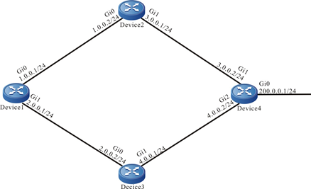
Figure 11–6 Networking of the IRMP unequal-cost load balancing
Configuration Steps
Step 1: Configure the IP address of the interfaces. (Omitted)
Step 2: Configure the IRMP.
#Configure Device1.
|
Device1#configure terminal
Device1(config)#router irmp 100
Device1(config-irmp)#network 1.0.0.0 0.0.0.255
Device1(config-irmp)#network 2.0.0.0 0.0.0.255
Device1(config-irmp)#exit
|
#Configure Device2.
|
Device2#configure terminal
Device2(config)#router irmp 100
Device2(config-irmp)#network 1.0.0.0 0.0.0.255
Device2(config-irmp)#network 3.0.0.0 0.0.0.255
Device2(config-irmp)#exit
|
#Configure Device3.
|
Device3#configure terminal
Device3(config)#router irmp 100
Device3(config-irmp)#network 2.0.0.0 0.0.0.255
Device3(config-irmp)#network 4.0.0.0 0.0.0.255
Device3(config-irmp)#exit
|
#Configure Device4.
|
Device4#configure terminal
Device4(config)#router irmp 100
Device4(config-irmp)#network 3.0.0.0 0.0.0.255
Device4(config-irmp)#network 4.0.0.0 0.0.0.255
Device4(config-irmp)#network 200.0.0.0 0.0.0.255
Device4(config-irmp)#exit
|
#View the IRMP neighbor inofrmation of Device1.
Device1#show ip irmp neighbor
IP-IRMP neighbors for process 100 Total neighbor 2
Address     Interface            Hold(s) Uptime     SeqNum   Srtt(ms) Rto(s)
1.0.0.2     gigabitethernet0  11        00:10:37  10           0            2
2.0.0.2     gigabitethernet1  12        00:10:15   9            0            2
#View the IRMP neighbor information of Device4.
Device4#show ip irmp neighbor
IP-IRMP neighbors for process 100 Total neighbor 2
Address     Interface                 Hold(s) Uptime    SeqNum   Srtt(ms) Rto(s)
3.0.0.1      gigabitethernet1      14        00:11:37 13           0            2
4.0.0.1      gigabitethernet2      12        00:10:45 12           0            2
Device1 successfully establishes the IRMP neighbor with Device2 and Device3, respectively. Device4 successfully establishes the IRMP neighbor with Device2 and Device3, respectively.
#View the topology table and routing table of Device1.
Device1#show ip irmp topology
IP-IRMP Topology Table for process 100
Codes: P - Passive, A - Active, H - Holddown, D - Hidden
        > - FIB route, * - FIB successor

P >1.0.0.0/24, 1 successors, FD is 2816
        *via Connected (2816/0), gigabitethernet0
P >2.0.0.0/24, 1 successors, FD is 2816
        *via Connected (2816/0), gigabitethernet1
P >3.0.0.0/24, 1 successors, FD is 3072
        *via 1.0.0.2 (3072/2816), gigabitethernet0
P >4.0.0.0/24, 1 successors, FD is 3072
        *via 2.0.0.2 (3072/512), gigabitethernet1
P >200.0.0.0/24, 2 successors, FD is 3328
        *via 2.0.0.2 (3328/3072), gigabitethernet1
        *via 1.0.0.2 (3328/3072), gigabitethernet0

Device1#show ip route
Codes: C - connected, S - static, R - RIP, O - OSPF, OE-OSPF External, M - Management
       D - Redirect, E - IRMP, EX - IRMP external, o - SNSP, B - BGP, i-ISIS

Gateway of last resort is not set

C 1.0.0.0/24 is directly connected, 13:16:35, gigabitethernet0
C 2.0.0.0/24 is directly connected, 13:19:24, gigabitethernet1
E 3.0.0.0/24 [90/3072] via 1.0.0.2, 00:03:22, gigabitethernet0
E 4.0.0.0/24 [90/3072] via 2.0.0.2, 00:22:01, gigabitethernet1
C 127.0.0.0/8 is directly connected, 22:27:25, lo0
E 200.0.0.0/24 [90/3328] via 2.0.0.2, 00:21:22, gigabitethernet1
                [90/3328] via 1.0.0.2, 00:03:22, gigabitethernet0
There are two load balancing routing to the network segment 200.0.0.0/24 in Device1 routing table. The forwarding paths to the network segment are Device1→Device2→Device4 and Device1→Device3→Device4.
Step 3: Change the interface delay.
#Change the bandwidth of the interface connected to Device1 and Device3 to 100000 kbps.
|
Device1(config)#interface gigabitethernet1
Device1(config-if-gigabitethernet1)#bandwidth 100000
Device1(config-if-gigabitethernet1)#exit
|
#View the topology table and routing table of Device1.
Device1#show ip irmp topology
IP-IRMP Topology Table for process 100
Codes: P - Passive, A - Active, H - Holddown, D - Hidden
        > - FIB route, * - FIB successor

P >1.0.0.0/24, 1 successors, FD is 2816
        *via Connected (2816/0), gigabitethernet0
P >2.0.0.0/24, 1 successors, FD is 25856
        *via Connected (25856/0), gigabitethernet1
P >3.0.0.0/24, 1 successors, FD is 3072
        *via 1.0.0.2 (3072/2816), gigabitethernet0
P >4.0.0.0/24, 1 successors, FD is 26112
        *via 2.0.0.2 (26112/2816), gigabitethernet1
P >200.0.0.0/24, 2 successors, FD is 3328
        *via 1.0.0.2 (3328/3072), gigabitethernet0
         via 2.0.0.2 (26368/3072), gigabitethernet1

Device1#show ip route
Codes: C - connected, S - static, R - RIP, O - OSPF, OE-OSPF External, M - Management
       D - Redirect, E - IRMP, EX - IRMP external, o - SNSP, B - BGP, i-ISIS

Gateway of last resort is not set

C 1.0.0.0/24 is directly connected, 28:44:11, gigabitethernet0
C 2.0.0.0/24 is directly connected, 00:14:05, gigabitethernet1
E 3.0.0.0/24 [90/3072] via 1.0.0.2, 00:10:11, gigabitethernet0
E 4.0.0.0/24 [90/28416] via 2.0.0.2, 00:07:57, gigabitethernet1
C 127.0.0.0/8 is directly connected, 220:26:51, lo0
E 200.0.0.0/24 [90/3328] via 1.0.0.2, 00:10:11, gigabitethernet0
After the metric offset is configured, Device1 preferentially chooses the routing 200.0.0.0/24 advertised by Device2.
Step 4: Configure the IRMP unequal-cost load balancing.
#Configure Device1 and configure the load balancing conversion factor as 100.
|
Device1(config)#router irmp 100
Device1(config-irmp)#variance 100
Device1(config-irmp)#exit
|
For details about the load balancing conversion factor, refer to the load balancing chapter in the IRMP function configuration.
Step 5: Check the result.
#View the topology table and routing table of Device1.
Device1#show ip irmp topology
IP-IRMP Topology Table for process 100
Codes: P - Passive, A - Active, H - Holddown, D Hidden
        > - FIB route, * FIB successor

P >1.0.0.0/24, 1 successors, FD is 2816
        *via Connected (2816/0), gigabitethernet0
P >2.0.0.0/24, 1 successors, FD is 28160
        *via Connected (28160/0), gigabitethernet1
P >3.0.0.0/24, 1 successors, FD is 3072
        *via 1.0.0.2 (3072/2816), gigabitethernet0
P >4.0.0.0/24, 1 successors, FD is 28416
        *via 2.0.0.2 (28416/2816), gigabitethernet1
P >200.0.0.0/24, 2 successors, FD is 3328
        *via 1.0.0.2 (3328/3072), gigabitethernet0
        *via 2.0.0.2 (26368/3072), gigabitethernet1

Device1#show ip route
Codes: C - connected, S - static, R - RIP, O - OSPF, OE-OSPF External, M - Management
       D - Redirect, E - IRMP, EX - IRMP external, o - SNSP, B - BGP, i-ISIS

Gateway of last resort is not set

C 1.0.0.0/24 is directly connected, 28:47:15, gigabitethernet0
C 2.0.0.0/24 is directly connected, 00:17:08, gigabitethernet1
E 3.0.0.0/24 [90/3072] via 1.0.0.2, 00:13:15, gigabitethernet0
E 4.0.0.0/24 [90/28416] via 2.0.0.2, 00:11:00, gigabitethernet1
C 127.0.0.0/8 is directly connected, 220:29:54, lo0
E 200.0.0.0/24 [90/3328] via 1.0.0.2, 00:13:15, gigabitethernet0
                       [90/26368] via 2.0.0.2, 00:00:12, gigabitethernet1
Routing 200.0.0.0/24 on Device1 forms the unequal-cost load balancing. Data will be transmitted for load balancing on these two paths based on the inverse ratio of the metric value.
 Switch


